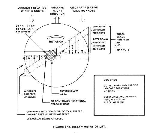
Note the shaded circle in the picture labeled "REVERSE FLOW":

Blade airspeed at the outboard edge of the shaded circle is 0 knots. Within the reverse flow area, the air actually moves over the blade backwards from trailing edge to leading edge. From the reverse flow area out to the blade tip, the blade airspeed progressively increases up to 294 knots.
At an aircraft airspeed of 100 knots, a 200 knot blade airspeed differential exists between the advancing and retreating blades. Since lift increases as the square of the airspeed, a potential lift variation exists between the advancing and retreating sides of the rotor disk. This lift differential must be compensated for, or the helicopter would not be controllable.
To compare the lift of the advancing half of the disk area to the lift of the retreating half, the lift equation can be used. In forward flight, two factors in the lift formula, density ratio and blade area, are the same for both the advancing and retreating blades. The airfoil shape is fixed for a given blade. The only remaining variables are changes in blade angle of attack and blade airspeed. These two variables must compensate for each other during forward flight to overcome dissymmetry of lift.
Two factors, rotor RPM and aircraft airspeed, control blade airspeed during flight. Both factors are variable to some degree, but must remain within certain operating limits. Angle of attack remains as the one variable that may be used by the pilot to compensate for dissymmetry of lift. The pitch angle of the rotor blades can be varied throughout their range, from flat pitch to the stalling pitch angle, to change angle of attack and to compensate for lift differential.
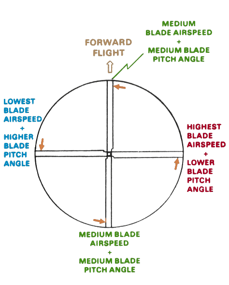
The following picture shows the relationship between blade pitch angle and blade airspeed during forward flight:

Note that blade pitch angle is lower on the advancing side of the disk to compensate for increased blade airspeed on that side. Blade pitch angle is increased on the retreating blade side to compensate for decreased blade airspeed on that side. These changes in blade pitch are introduced either through the blade feathering mechanism or blade flapping. When made with the blade feathering mechanism, the changes are called cyclic feathering. Pitch changes are made to individual blades independent of the others in the system and are controlled by the pilot's cyclic pitch control.
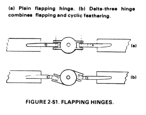
The delta hinge is not oriented parallel to the blade chord:

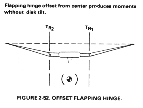
It is designed so that flapping automatically introduces cyclic feathering which corrects for dissymmetry of lift. The offset hinge is located outboard from the hub:

The offset hinge uses centrifugal force to produce substantial forces that act on the hub. One important advantage of offset hinges is the presence of control regardless of lift condition, since centrifugal force is independent of lift.